

I've received a lot of questions over the years since Bluetooth 5 was released about how the "2x speed" actually works and what to expect in terms of realistic speeds (as opposed to theoretical speeds). So, in this post, I'm going to break it all down for you. We'll cover:
- What's the practical throughput to expect from Bluetooth LE?
- Bluetooth 5's new 2M PHY for data transfer
- What are the factors that impact/determine data throughput?
- How do you calculate your application data throughput?
- How do you maximize your data throughput?
- Testing, measuring, and calculating data throughput using two nRF52 series development kits
Key things to know about Bluetooth 5 speeds
Before we dive in too deep, let's get a few things straight:
- The Bluetooth 5 “2x speed” feature may require a hardware/stack update so older devices/chips/modules may not support it (refer to your chipset's datasheet). It is also important to note that in order to achieve this higher throughput you will need each of the two Bluetooth devices communicating with each other to support the new LE 2M PHY (which makes it possible to transfer data at this higher rate).
- The new LE 2M PHY, as well as the original LE 1M PHY, are both called Uncoded PHYs since they use a 1-symbol representation per bit of data (in comparison to the new LE Coded PHY which uses a 2-symbol or 8-symbol representation per bit of data).
- When utilizing the higher-speed PHY, you actually achieve lower power consumption (given that you transfer the same amount of data). This is because the radio-on time is reduced without the transmit power being increased. This in turn also improves coexistence with other wireless technologies within the 2.4 GHz spectrum (also due to the reduced radio-on time).
Why is it impossible to achieve theoretical Bluetooth speeds?
First, we need to understand that the speeds advertised are only theoretical and are cut down when it comes down to application data throughput. The data rates of 1 Mbps (LE 1M PHY), 2 Mbps (LE 2M PHY), 125 kbps, and 500 kbps (both using the LE Coded PHY with S=8 and S=2, respectively) are the rates at which the radio transmits data, but this is not achievable for the application throughput due to the following reasons:
- Limit on the number of packets per connection interval
- Inter Frame Space (IFS) delay between packets (150 us)
- Empty packets are required to be sent from a device even if no data is available for transmission
- Packet overhead - not all bytes in a packet are used for payload
In order to better understand these factors and understand what impacts application throughput, we have to take a deeper look at the packet format. The following figure shows what LE 1M PHY and 2M PHY data packets look like:
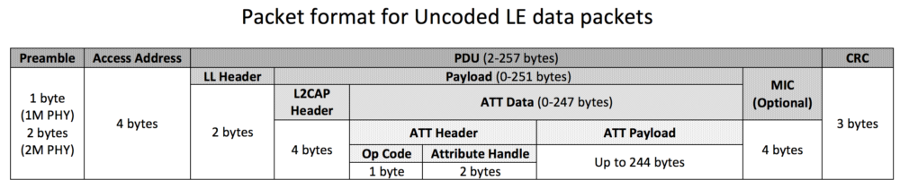
The part we’re interested in (and the one that really defines the application data) is the ATT Payload. As you can see from the figure, there are a number of overhead bytes that are used by each layer in Bluetooth Low Energy.
- In 4.0 and 4.1, the maximum ATT Payload is 20 bytes.
- In 4.2 and 5.0, a new feature called Data Length Extensions (DLE) allows the ATT Payload to hold up to 244 bytes of data.
Bluetooth 5 speed: 2x speed utilizing the new 2M PHY
It is useful to understand the limitations of using the new LE 2M PHY in Bluetooth 5:
- Cannot be used to transmit the primary advertisements (on the primary channels).
- Can be used for the secondary “auxiliary packets” sent on the same channels as the data packets (37 channels: 0-36).
To learn more about primary and secondary advertisements, refer to my previous blog post: Bluetooth 5 Advertisements: Everything you need to know. - LE 1M is mandatory, whereas LE 2M is optional. So, not all chipsets claiming Bluetooth 5 support can necessarily handle the higher throughput.
- Advertisements and discovery can occur on the LE 1M PHY, and then connections occur on the secondary advertisement channel using the LE 2M PHY
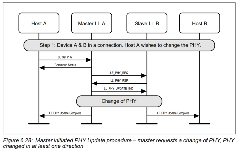
Transfer of application data from one device to another usually happens during a connection between the two Bluetooth devices. The connected devices can negotiate the use of a different PHY via the PHY Update Procedure. It can be initiated by either Peripheral or Central after a connection is established, but the Central will ultimately make the final decision on which PHYs are used for each direction (based on the Peripheral's request and the PHYs the Central supports).
Factors that impact/determine the data throughput for Bluetooth devices
There are a few factors that impact the data throughput of a Bluetooth Low Energy application. The most common are:
- PHY being used (LE 1M vs. LE 2M vs. LE Coded (S=2 or S=8))
- Connection interval
- Maximum number of packets per connection interval
- ATT Maximum Transmission Unit (ATT MTU)
- Data Length Extension (DLE)
- Operation type: Write with response vs. Write without response, Indications vs. Notifications
- Inter Frame Space (IFS): time gap between consequent packets (150 us)
- Transmission of empty packets
- Packet overhead - not all bytes, in a packet, are used for the application payload
Let’s go over each of these in more detail.
PHY
There are basically three PHYs in Bluetooth 5: the original 1 Mbps PHY, the new 2 Mbps, and the Coded PHY (with S=2, or S=8 configuration).
The PHY used will directly impact the maximum data throughput you can achieve since it determines the actual raw data rate at which packets are sent over the air.
Connection Interval & max packets per connection event
The connection interval effectively determines how many packets can be sent during one connection event. The higher the value, the more packets can be sent in one connection event (up to a certain limit for some devices).
Learn more about connection intervals: Bluetooth LE connection intervals and events
However, the number of packets per connection event depends on the device and Bluetooth Low Energy stack so it is limited and differs between devices and stack versions on a specific device.
This value also depends on the operation of the device, so the radio may have to attend to other events and the number of packets sent per connection events may not reach the max allowed by the stack. For example, the number differs between iOS and Android and also changes depending on the version of the OS running on the device.
Sometimes it is useful to dynamically update the connection parameters based on the use case. However, keep in mind that it is up to the Central to accept these recommendations or update the parameters to accommodate them.
Data Length Extensions (DLE)
This feature allows the packet size to hold a larger amount of payload (Up to 251 bytes vs. 27 when disabled). This feature was introduced in version 4.2 of the Bluetooth Core specification.
ATT Maximum Transmission Unit (ATT MTU)
ATT MTU Determines the max amount of data that can be handled by the transmitter and receiver and which they can hold in their buffers.
The MTU value affects the amount of overhead data (specifically the ATT header which is 3 bytes). The minimum ATT MTU allowed is 27 bytes. This allows a max of 20 bytes of ATT payload (3 bytes are used for the ATT header, and 4 bytes for the L2CAP header).
There is no limit per the spec on how high the MTU value can be, but the specific stack in use may have its own limitations. Typical values are in the range of 512 bytes.
For example, if you enable DLE then you can transfer up to 251 - 4 = 247 bytes (after deducting the L2CAP Header size). After taking into account the ATT header (3 bytes), we are left with 244 bytes for the actual ATT payload data. If the MTU is at least 247 bytes then the MTU will fit into one single packet.
If the MTU is greater than 247 bytes and the data is also larger than that, then the ATT payload will span multiple packets causing the throughput to go down (because of the packet overhead and timing in between the packets).
The effective MTU gets determined by the minimum value of ATT MTU that the client and server support. For example, if a client supports an ATT MTU of 100 bytes and the server responds that it supports an ATT MTU of 150 bytes, then the client will decide that the ATT MTU to be used for the connection from thereon is 100 bytes.
Operation type: Write with response vs. write without response, Indications vs. Notifications
If high throughput is desired then we can use Write without response or Notifications to transfer the data from the client to the server and from the server to the client. These operations remove the need for the other device to acknowledge receipt of the data at the application layer and respond before the next block of data can be sent.
Inter Frame Space (IFS): time delay between consecutive packets (150 us)
From the Bluetooth specification:
Transmission of empty packets
If the device receiving data has no data to send back, it still needs to send an empty packet as per the Bluetooth specification.
Packet overhead
As we saw in the packet format figure, the packet includes some overhead data that doesn't count toward your application data (ATT data). Basically, these bytes will consume part of your transfer data rate while not accounting for any bytes being sent as part of your application data.
Calculating your application data throughput
The big question is: how do we calculate our application throughput?
As we mentioned before, there are a few variables that impact the data throughput:
- Bluetooth version & PHY used
- DLE: Data Length Extensions - enabled or not
- ATT MTU value
- Connection interval
- Maximum number of packets per connection event
- Operation (writes with responses vs. writes without responses, and notification vs. indication)
- Inter Frame Space (IFS): 150 microseconds
The Bluetooth version and PHY determine the raw data transfer rate. For example, if we are using Bluetooth version 4.2 and the LE 1M PHY, then the transfer rate is at 1 Mbps. If on the other hand, we are using the Bluetooth 5 LE Coded PHY with S=8, then the data rate goes down to 125 kbps.
The DLE, ATT MTU, connection interval, the maximum number of packets per connection interval, Operation, and IFS all determine the portion of the on-radio time that's utilized for actual data transfer.
The packet format plays a big role in how much of the data being transferred is your actual application data. The LE 1M PHY and LE 2M PHY both have a similar packet format. The LE Coded PHY has a significantly different packet format, so we'll be looking at these two cases separately.
LE 1M PHY and LE 2M PHY calculation
Referring back to the packet format for LE Uncoded PHYs:

The amount of overhead for each PHY is slightly different. The Preamble is 1 byte in the case of the 1M PHY and 2 bytes in the case of the 2M PHY. The MIC field is an optional field that is used only for encrypted connections. For simplicity, we will only consider unencrypted connections - for the encrypted case, it simply adds 4 bytes of overhead.
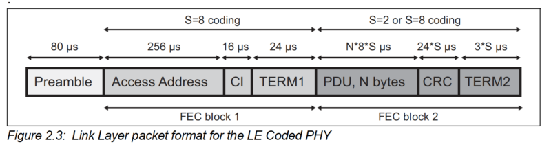
For LE Coded PHYs, the packet format looks like this (from the Bluetooth Core spec Vol 6, Part B, Section 2.2):
Steps for calculating the throughput (in Mbps):
For sake of simplicity, we assume the following:
- Encryption is NOT enabled (the MIC field is not included in the packet)
- We are interested in the throughput for one direction (e.g. Central to Peripheral), so we assume the other direction only transfers empty packets
- Writes without responses (which would help in maximizing the throughput when transferring large amounts of data
Steps:
Step 1: Determine the PHY being used and note down the rate of raw data transfer
E.g. for 1M PHY → 1 Mbps, for Coded PHY and S=8 → 125 kbps
Step 2: Determine the time it takes to send one data packet and the empty packet from the receiver.
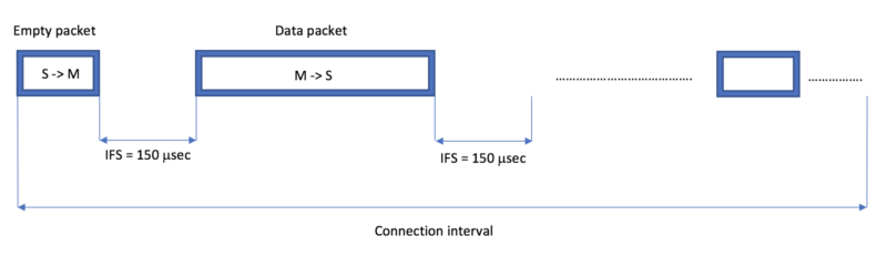
The time during which one data packet can be sent will include the following:
Data_Packet_Time = Time to transmit empty packet + IFS + Time to transmit the actual data packet + IFS.
An empty packet transmission time can be calculated as follows:
Time to transmit empty packet = empty packet size / raw data rate
An empty packet will contain the following fields:
Preamble + Access Address + LL Header + CRC.
For 1M PHY, Preamble will be 1 byte, and so the total size of the empty packet = 1 + 4 + 2 + 3 bytes = 10 bytes = 80 bits.
(for 2M PHY, the size of an empty packet will be 88 bits since the Premable is 2 bytes instead of 1 byte).
Based on this, the time to transmit an empty 1M PHY packet will be:
Time to transmit empty packet = empty packet size / raw data rate = 80 bits / 1 Megabits per second = 80 microseconds
A data packet will contain all fields listed in the packet format diagram with the exception of the MIC field (encryption disabled).
Time to transmit data packet = data packet size / raw data rate
If we have DLE enabled and the ATT MTU is equal to the maximum bytes allowed in one packet: 247 bytes, then we can calculate the data packet size as:
Data packet size = 1 + 4 + 2 + 4 + 247 + 3 bytes = 265 bytes = 265 x 8 bits = 2120 bits
Time to transmit data packet = 2088 bits / 1 Mbps = 2,120 microseconds
Data_Packet_Time = Time to transmit empty packet + IFS + Time to transmit the actual data packet + IFS = 80 + 2 x 150 + 2120 = 2,500 microseconds
For comparison, in the case of 2M PHY, it would be:
Data_Packet_Time = Time to transmit empty packet + IFS + Time to transmit the actual data packet + IFS = 88/2 + 2 x 150 + (2 + 4 + 2 + 4 + 247 + 3) x 8/2 = 1,392 microseconds
When DLE is enabled and the ATT MTU is set to less than 247, we end up with more overhead (since now data larger than the ATT MTU gets split up into more packets).
For example, say we have the ATT MTU set to 158, then in order to transfer 244 bytes of application data, we will need two packets instead of one, causing the throughput to go down due to the increased byte overhead as well as the increased IFS between the packets.
In another scenario, we could have DLE disabled (Payload size up to 27 bytes) and the ATT MTU greater than 27 bytes.
Here, this will also result in more packets needing to be sent for the same amount of data, causing the throughput to go down.
Note: The same method for calculating the data and empty packet sizes that we used above can be used for the LE Coded PHY.
Step 3: Figure out how many packets can be transmitted during one connection interval
This calculation is not always purely mathematical - you will need to take into account the limitations of the stack and device being used. iOS and Android have maximums that change with OS version, so it's not always easy to figure out.
That being said, on an MCU, the vendor's SDK usually lists the maximum in their documentation. It's also helpful to do a trial and error and figure out what your specific device supports.
Once you've figured out the maximum, you can calculate the maximum theoretical number of packets that would fit within a connection interval of choice.
For example, if we had a connection interval of 7.5 milliseconds (the lowest permitted by the spec), then for our example above (using 1M PHY, DLE enabled):
Maximum # of data packets per connection interval = [connection interval / Data_Packet_Time], where [ ] rounds to the highest whole number (integer)
Maximum # of data packets per connection interval = [7.5 x 1,000 microseconds / 2,468 microsecs] = 3 packets
Usually, this number is not realistic as there are timing delays between packets being sent on consecutive connection events.
So, for our example, we will go with 2 packets instead of 3.
Step 4:
Once we've figured out the maximum # of data packets that can be transferred per connection interval, we can calculate the data throughput:
Data throughput = data per connection interval ÷ connection interval
= (No. of data packets per connection interval x Data size per packet) ÷ connection interval
= 2 x 244 x 8 bits / 7.5 milliseconds = 520,533 bits/sec ~= 508 kbps
Testing and calculating data throughput between two nRF52 development kits
In this section, we will run multiple tests of data transfer, calculate the throughput using the procedure we described earlier, and then compare them with the measured throughput reported by the application running on the development boards.
The tests are run based on the demo app provided by Nordic Semiconductor and featured in this blog post: Throughput and long-range demo.
The source code for the example can be found on the GitHub page here.
Case 1 (PHY: 1 Mbps, ATT MTU = 23 bytes, DLE: enabled, Connection interval: 7.5 millisecs)
Data throughput reported by firmware:
Calculated data throughput:
With the MTU set to 23 bytes, DLE does not really affect the data throughput and packet sizes.
Time to transmit data packet = data packet size / raw data rate = 1 + 4 + 2 + 4 + 23 + 3 bytes / 1 Mbps= 37 x 8 bits / 1 Mbps = 296 microsecs
Data_Packet_Time = Time to transmit empty packet + IFS + Time to transmit the actual data packet + IFS = 80 + 150 + 296 + 150 microsecs = 676 microsecs
Maximum # of data packets per connection interval = [connection interval / Data_Packet_Time] = [7.5 millisecs / 676 microsecs] = [11.09] = 11 packets
Total data transferred per connection interval = 11 x 20 bytes = 11 x 20 x 8 bits = 1,760 bits
Data throughput = Total data transferred per connection interval/connection interval = 1760 bits / 7.5 millisecs = 234.67 Kbits/s
As we can see, the calculated value and measured value are pretty close.
Case 2 (PHY: 2 Mbps, ATT MTU = 23 bytes, DLE: enabled, Connection interval: 7.5 millisecs)
Data throughput reported by firmware:
Calculated data throughput:
Time to transmit data packet = data packet size / raw data rate = 2 + 4 + 2 + 4 + 23 + 3 bytes / 2 Mbps= 38 x 8 bits / 2 Mbps = 152 microsecs
Data_Packet_Time = Time to transmit empty packet + IFS + Time to transmit the actual data packet + IFS = 44 + 150 + 152 + 150 microsecs = 496 microsecs
Maximum # of data packets per connection interval = [connection interval / Data_Packet_Time] = [7.5 millisecs / 512 microsecs] = [15.12] = 15 packets
Total data transferred per connection interval = 15 x 20 bytes = 15 x 20 x 8 bits = 2400 bits
Data throughput = Total data transferred per connection interval/connection interval = 2400 bits / 7.5 millisecs = 320 Kbits/s
As we can see, the calculated value and measured value are pretty close.
Case 3 (PHY: 1 Mbps, ATT MTU = 158 bytes, DLE: enabled, Connection interval: 7.5 millisecs)
Data throughput reported by firmware:
Calculated data throughput:
Time to transmit data packet = data packet size / raw data rate = 1 + 4 + 2 + 4 + 158 + 3 bytes / 1 Mbps= 172 x 8 bits / 1 Mbps = 1376 microsecs
Data_Packet_Time = Time to transmit empty packet + IFS + Time to transmit the actual data packet + IFS = 80 + 150 + 1376 + 150 microsecs = 1756 microsecs
Maximum # of data packets per connection interval = [connection interval / Data_Packet_Time] = [7.5 millisecs / 1756 microsecs] = [4.27] = 4 packets
Total data transferred per connection interval = 4 x 155 bytes = 4 x 155 x 8 bits = 4960 bits
Data throughput = Total data transferred per connection interval/connection interval = 4960 bits / 7.5 millisecs = 661.33 Kbits/s
Case 4 (PHY: 2 Mbps, ATT MTU = 247 bytes, DLE: enabled, Connection interval: 7.5 millisecs)
Data throughput reported by firmware:
Calculated data throughput:
Time to transmit data packet = data packet size / raw data rate = 2 + 4 + 2 + 4 + 247 + 3 bytes / 2 Mbps= 262 x 8 bits / 2 Mbps = 1048 microsecs
Data_Packet_Time = Time to transmit empty packet + IFS + Time to transmit the actual data packet + IFS = 44 + 150 + 1048 + 150 microsecs = 1392 microsecs
Maximum # of data packets per connection interval = [connection interval / Data_Packet_Time] = [7.5 millisecs / 1392 microsecs] = [5.39] = 5 packets
Total data transferred per connection interval = 5 x 244 bytes = 5 x 244 x 8 bits = 9760 bits
Data throughput = Total data transferred per connection interval/connection interval = 9760 bits / 7.5 millisecs = 1301.33 Kbits/s
Important Note: In the last two cases, the number of packets per connection interval is small and any difference between what we calculate and what is measured will have a big impact on actual data throughput.
For example, if the number of packets per connection interval ends up being 4 instead of 5 in Case #4, the calculated throughput becomes 1,041.1 Kbps instead of 1,301.33 Kbps (which is a big difference and could explain the discrepancy in numbers here).
Case 5 (PHY: 2 Mbps, ATT MTU = 247 bytes, DLE: enabled, Connection interval: 50 millisecs)
Data throughput reported by firmware:
Calculated data throughput:
Time to transmit data packet = data packet size / raw data rate = 2 + 4 + 2 + 4 + 247 + 3 bytes / 2 Mbps= 262 x 8 bits / 2 Mbps = 1048 microsecs
Data_Packet_Time = Time to transmit empty packet + IFS + Time to transmit the actual data packet + IFS = 44 + 150 + 1048 + 150 microsecs = 1392 microsecs
Maximum # of data packets per connection interval = [connection interval / Data_Packet_Time] = [50 millisecs / 1392 microsecs] = [35.92] = 35 packets
Total data transferred per connection interval = 36 x 244 bytes = 35 x 244 x 8 bits = 68320 bits
Data throughput = Total data transferred per connection interval/connection interval = 70272 bits / 50 millisecs = 1366.4 Kbits/s
Case 6 (PHY: 2 Mbps, ATT MTU = 247 bytes, DLE: enabled, Connection interval: 400 millisecs)
Data throughput reported by firmware:
Calculated data throughput:
Time to transmit data packet = data packet size / raw data rate = 2 + 4 + 2 + 4 + 247 + 3 bytes / 2 Mbps= 262 x 8 bits / 2 Mbps = 1048 microsecs
Data_Packet_Time = Time to transmit empty packet + IFS + Time to transmit the actual data packet + IFS = 44 + 150 + 1048 + 150 microsecs = 1392 microsecs
Maximum # of data packets per connection interval = [connection interval / Data_Packet_Time] = [400 millisecs / 1392 microsecs] = [287.36] = 287 packets
Total data transferred per connection interval = 287 x 244 bytes = 287 x 244 x 8 bits = 560224 bits
Data throughput = Total data transferred per connection interval/connection interval =560224 bits / 400 millisecs = 1400.56 Kbits/s
Optimizing for maximum Bluetooth device data throughput
Based on the factors we went over, we can note the following when optimizing for high data throughput:
- Always enable DLE
Obviously, if you're using Bluetooth v4.1 or earlier, this is not a valid option. In general, however, make sure you enabled DLE to maximize your packet-to-application data efficiency - Use LE 2M PHY
If you know that the devices on both ends support Bluetooth 5, then utilizing the LE 2M PHY is one of the best ways to maximize your application data throughput. Using the LE 2M PHY will also help your device have low power consumption (and therefore, a longer battery life!), so you hit two birds with one stone! - Use Notifications and Writes without Responses
Utilizing these will help remove any unnecessary packets being transmitted (compared to Indications and normal Writes (with responses) which require the receiving end to acknowledge each packet received). - Choose an ATT MTU value of at least greater than 247 bytes
This will minimize any overhead in packet bytes. - Choose a connection interval that allows for the maximum # of packets per connection interval
But keep in mind that the connection interval affects power consumption. The shorter the interval, the more power your device will consume because of the increased radio-on time.You also want to make sure you don't choose an interval that's too high, otherwise, it'll compromise the user experience (higher connection interval results in higher latency).One last thing to make sure you account for is any limitations of the devices in your system in terms of the maximum number of packets per connection interval supported.
Summary & closing
The calculated values we listed above are still theoretical and may not align with the measured data throughput in practice and real-life environments, but they still are a good starting point and give a good indication of what to expect (at least for a maximum).
Interference and transmission/reception errors also affect data throughput (retries, data loss, and closing of connection events result in lower throughput).
These can be caused by the presence of other devices utilizing the same 2.4 GHz band as Bluetooth Low Energy, longer distance between devices, the existence of obstacles between devices, and more...


